Chapter 3
Numerical Simulation of Collisionless Shocks

The Rankine-Hugoniot equations (Section 1.4.1) describe macroscopic shock structure in terms of conserved quantities, but do not provide any description of the finite width of the shock transition or the field structures that appear there. It is difficult to produce analytic descriptions of the micro-physics of shock structure, since many of the processes occurring at the shock front are non-linear and difficult to describe analytically. In order to study the shock transition, therefore, numerical simulation becomes a useful tool.
I this chapter, we describe various classes of plasma simulation algorithms and discuss the different methods that can be used to stimulate the formation of a shock wave. We discuss in detail the hybrid model for simulating plasmas and the CAM-CL hybrid algorithm, which we use in this thesis. In order to examine electron behaviour in the shock, we use a test particle code to study electron motion in the fields generated by our hybrid code. We therefore describe and compare a number of algorithms for integrating electron trajectories and interpolating fields in time and space.

3.1  Shock Simulation Methods

In order to simulate a shock, we need to determine a set of initial conditions that will result in the creation of a shock. We also need to choose a plasma simulation model to evolve these initial conditions in time. We describe various classes of plasma simulation algorithms and discuss the different methods that can be used to stimulate the formation of a shock wave. We shall discuss the plasma simulation model first, since this may influence the choice of initial conditions.

3.1.1  Plasma simulation models

Plasma simulation models work by using Maxwell's equations to calculate the electric and magnetic fields from the currents and charges. In a kinetic simulation, these come from the moments of the particle distribution. The particle distribution itself can be treated in a variety of ways. The particles can be simulated directly as a collection of "macro-particles", they can be approximated as a phase space distribution, or a fluid approximation can be used to represent the particles in terms of their moments. Below we describe the characteristics of a variety of different models and discuss which is most suitable for our simulations.
When selecting a plasma simulation model, we should consider which physical processes are relevant, and which will have little impact on what we are studying. In terms of collisionless shocks, there are a number of issues. The first is that the profile of the shock transition, including the shock foot, ramp and overshoot, is produced by kinetic ion physics, not electron physics. We also need to ensure that the simulation box can be large enough to enclose any field structure caused by ion phenomena. Since we are hoping to study electron acceleration, we also need the simulation to run for sufficiently long that electrons can interact with, and escape from, the shock. Finally, we should consider the role that electron kinetic physics might play in the electron acceleration process.

Magnetohydrodynamics

A typical MHD code will model the plasma as a fluid using only first order moments of the distribution function, so the fluid's properties are characterised in terms of its position and velocity. The MHD equations for a perfectly conducting (ideal) plasma are shown below. The plasma fluid is described by the continuity, momentum and energy equations respectively:
 D r

Dt
= - rÑ·U
(3.1)

r  D U

Dt
= - Ñp +  1

m0
(Ñ×B) ×B
(3.2)

 D

Dt
(p r-g) = 0
(3.3)
The magnetic field is described by two equations that are derived from Maxwell's equations:
 B

t
= Ñ×(U ×B)
(3.4)

Ñ×B = m0 J
(3.5)
The electric field is not described in these equations, although it can be calculated from Equation 3.4.
Plasmas can be simulated under the MHD fluid approximation by evolving the MHD equations stepwise. Such MHD codes only require the storage and evolution of two scalar and two vector quantities for each grid cell. They are therefore well suited to very large computational domains and can be used to examine the macroscopic behaviour of plasma parameters over large distances. These codes do not, however, take into account the form of the particle distribution function and cannot therefore take into account kinetic processes. This makes them much less suitable for studying boundaries and transitions, such as the shock surface, where the micro-physics of the particle distribution is responsible for the field structure.

Vlasov equation

The Boltzmann equation, which describes the evolution of the particle distribution function, fs, in phase space and incorporates all kinetic effects, is
 fs

t
+ v·Ñfs +  qs

ms
(E + v ×B) ·  fs

v
= æ
è
 fs

t
ö
ø


coll 
(3.6)
The collision term on the right hand side of the equation is set to zero for collisionless plasmas, yielding the Vlasov equation. In Vlasov codes, it is the phase space distribution of particles that is modelled. The distribution function of each particle species is calculated on a grid at each individual point in phase space, f(x,v,t). These distribution functions are then evolved using the governing differential equations, so that ion and electron kinetic physics is simulated in a self-consistent manner.
Vlasov codes must therefore use a time step that allows the electron gyroperiod to be resolved. A particle's gyroperiod is given by:
Ws =  qsB

ms
(3.7)
The proton-electron mass ratio is mp/me » 1800. This places a huge constraint on Vlasov codes, since the simulation of ion kinetic effects using electron time scales requires the number of time steps to increase by a factor of 1800. A similar argument applies to electron and ion length scales. This can make it difficult to obtain quantitative results for processes such as electron acceleration in shocks which depend on the interaction of electron and ion scale phenomena.
An additional drawback to the Vlasov method is that a great deal of information is required in order to adequately represent the distribution functions. This is a particular problem at the shock transition where ion temperatures can increase by factors of around fifty, requiring large grid domains in velocity. It would be very difficult to represent adequately the distribution function over such a large range of velocity, making Vlasov codes unsuitable for our simulations.

Full particle codes

In contrast to the MHD fluid approximation, full particle codes simulate both ion and electron species as a collection of macroparticles. This means that, in common with Vlasov codes, both ion and electron kinetic physics are treated in a self-consistent manner. In contrast to Vlasov codes, however, there is no discretisation of velocity. Full particle codes are therefore better at modelling processes, such as particle acceleration at shocks, in which a considerable fraction of the particle population have trajectories that carry them through a large velocity range.
In common with Vlasov codes, full particle codes also need to be run with time and length scales that can model both ion and electron phenomena. In order to overcome this, the mass ratio is often artificially lowered to a value where electron and ion frequencies are adequately separated, but computational expense is more reasonable. For example, Krauss-Varban et al. [1995] used a mass ratio of mp/me = 400 to run a 20,000 time step quasi-perpendicular shock simulation, lasting 6 Wi-1. In our simulations, however, we are attempting to accelerate electrons to considerable energies at which their gyroradii become comparable with that of a thermal proton. At these energies we might expect coupling between electron trajectories and ion processes, so altering the mass ratio and hence the associated length scales would make it difficult to compare our results with observations.
Electrons interact with the shock for a number of ion gyroperiods and over ion distance scales. It would be difficult to run a full particle code for sufficiently long and over sufficient distances to study electron acceleration effectively. It would also be difficult to have sufficient disk storage for the fields required for a test particle simulation. This is because, in order to resolve electron scale processes, the fields would need to be stored on electron time scales. The only way to run a test particle simulation would therefore be to run the test particle code concurrently with the full particle simulation. This would be computationally very complicated, would impose large memory constraints, and would be inefficient in terms of varying the test particle initial conditions.
Full particle codes also suffer from noise due to the approximation of a large number of particles by a small number of macroparticles. Although this affects all simulations that use macroparticles, it can be particularly acute for full particle codes because the already severe computational constraints mean that the number of particles per cell is kept as low as possible. This can introduce a high level of artificial electron scattering.
Lembege & Savoini [1999] ran simulations of electron acceleration at shocks with a mass ratio of mp/me » 40 and with an initial particle density of 4 particles per cell. The duration of the simulations was around 18  Wi-1, so that electron acceleration could be studied. The simulation box was, however, too narrow to observe ion scale ripples. They found that electron scale ripples were produced at the shock front, which they believe are due to the excitation of lower-hybrid waves. They also found that electron heating varied with qBn, but that this relationship depended on the mass ratio. This demonstrates that full particle codes are able to simulate shock properties on electron scales. This is, however, at a cost of introducing numerical dependencies that make any comparison with observations very difficult.
Full particle codes are, at first sight, an attractive option. The practical restrictions placed on us by having finite computational resources, however, mean that they are not suitable for the study of electron acceleration in shocks.

Hybrid approximation

Hybrid codes provide a compromise between the Vlasov and full particle methods. In a hybrid code, ions are treated as macroparticles, whilst electrons are simulated as a fluid. Electron kinetics are thus neglected and modes such as lower-hybrid waves cannot be simulated. A hybrid code is also unable to model electron scale ripples, which are seen in some full particle simulations. Hybrid codes suffer from noise in a similar way to full particle codes. It is, however, more computationally feasible to increase the number of particles per cell, so this noise may be reduced. A clear advantage of hybrid codes is the relative ease with which time scales that are sufficient for electron acceleration may be simulated.
A hybrid algorithm is generated using the following equations. The velocity, vs, of a particle of species s is
 dxs

dt
=vs
(3.8)
We are interested in the electromagnetic behaviour of the plasma, and not the propagation of light waves, so we can use the Darwin approximation. This removes the displacement current from Maxwell's equations, which become
 B

t
=-Ñ×E
(3.9)

Ñ×B=m0J
(3.10)
Ions are accelerated according to the Lorentz force law and we use an equation of motion for the electron fluid:
 dvs

dt
=  qs

ms
(E+vs×B)
(3.11)

neme  dUe

dt
=-neeE+Je×B-Ñpe
(3.12)
Finally, in order to close the system, we need an equation of state for the electron fluid. The shock structure is determined by the ion physics, with the electrons providing quasi-neutrality. It is therefore appropriate to use a simple isothermal equation of state:
pe=nekBTe
(3.13)
The observational evidence is that hybrid codes are able to model quasi-perpendicular shocks well. The hybrid code is the best compromise for our purposes because it allows ion scale physics to be incorporated at manageable computational cost. In order to achieve this, we must sacrifice the ability to study electron kinetic effects. Despite not playing a role in determining large scale shock structure, it is possible that such effects might couple with the electron population. We are, however, able to generate high resolution results for sufficiently long that electron test particle codes can be successfully run in the resulting fields.

3.1.2  Shock generation

After selecting a plasma simulation algorithm, we need to determine suitable initial conditions for launching a shock into the simulation box. In doing this, we should consider whether we are artificially constraining our simulations and whether the properties of the simulation box will provide output which is useful to us. For example, in our case we want to integrate electron trajectories in our simulation box for a considerable time, starting from upstream of the shock and finishing either upstream or downstream. We describe two different approaches. The first requires the shock to be established using an analytic function as a representation of the shock structure. The second method allows the shock to form in a self-consistent manner by allowing plasma to collide with a boundary.

Rankine-Hugoniot conditions

It is possible to set up a shock by specifying upstream and downstream conditions using the Rankine-Hugoniot equations [Leroy et al., 1981,Leroy et al., 1982]. These equations, shown in Section 1.4.1, describe the shock in terms of conserved quantities. A thin transition region is introduced in order to link the upstream and downstream and to represent the finite width of the shock transition. This method, however, has the drawback that it is not self-consistent and that both the downstream distribution and the simulation boundary conditions are prescribed only in terms of the lowest-order ion velocity moments [Winske & Omidi, 1996]. This makes Rankine-Hugoniot initial conditions suitable for MHD codes, but less suitable for kinetic simulations.

Dynamic creation

sim_config
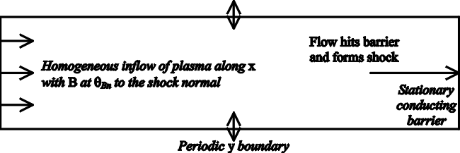
Figure 3.1: A diagram of the simulation box and initial conditions that we use in order to generate a shock wave.
Our numerical studies of shocks work by setting up a shock structure and following the paths taken by a number of test particles. These results can then be used to build up a statistical picture of the variation of the particle distribution function throughout the shock. The conditions that we use to generate a shock are illustrated in Figure 3.1. We generate a shock by reflecting homogeneous plasma, moving at constant velocity, off a stationary perfectly conducting barrier. This is a standard method for launching a shock that is physically simple, but which provides a clean shock once the shock front is clear of the reflecting barrier. It is also easy to set up this configuration, since the initial magnetic field is guaranteed to have Ñ·B = 0 and the shock parameters may easily be changed by changing the composition and speed of the initial uniform plasma. The method is self-consistent, and makes no assumptions about the nature of the downstream distribution.
Our implementation does have some limitations. The shock is planar, although it is possible to approximate a curved shock by varying qBn along the shock [Krauss-Varban & Burgess, 1991]. For simplicity we use an upstream plasma that is smooth, so we are neglecting upstream waves and bulk inhomogeneity. The final limitation, which is intrinsic to this method, is the presence of the downstream barrier. This prevents us from modelling wave sources there.
A variation on the stationary barrier is the use of a piston to drive the shock. This can be achieved by using a simulation box similar to that in Figure 3.1, but keeping the plasma stationary and replacing the reflecting barrier with a moving piston. In many respects, this is equivalent to a simple frame transformation, but allows the use of a curved piston to produce a curved shock wave. It also eliminates the need to create plasma at the inflow boundary throughout the course of the simulation. This can be particularly important in full particle codes, where computational constraints severely limit the number of particles that can be simulated. The disadvantage to this approach is that, as a result of the frame transformation, the shock leaves the simulation box earlier. We wish to provide electrons with the maximum possible time to interact with the shock front, and this drawback makes this variation unsuitable.

3.2  The CAM-CL Hybrid Algorithm

The Current Advance Method/Cyclic Leapfrog algorithm [Matthews, 1994] is a hybrid scheme that makes the following additional assumptions: firstly, that the electron fluid is inertialess:
me = 0
(3.14)
and secondly, that the electron fluid provides quasi-neutrality:
nee = rc =
å
s 
nsqs
(3.15)
Under these approximations, the hybrid equations simplify. We can re-write the expression for an electric field as a state function, so that we can calculate it directly from moments of the ion distribution. Using Equations 3.10 and 3.12 we obtain:
E=  (Ñ×BB

m0 rc
-  Ji×B

rc
-  Ñpe

rc
(3.16)
where the quantity Ñpe is calculated using the isothermal electron equation of state and the assumption of quasi-neutrality, Equations 3.13 and 3.15.
The CAM-CL algorithm consists of three parts. The particle push uses a leapfrog method to advance ion velocities and to calculate their trajectories. The current advance method is used to collect particle moments in the same computational pass through the particle arrays as the particle push. The cyclic leapfrog method is used once moments have been collected to evolve the fields using a sub-stepping technique that allows many field advances to be conducted per ion time step, thus allowing waves of higher frequencies to be simulated.

Particle push

Ion positions and velocities are advanced using a leapfrog scheme, which has the advantage of being second order. This means that the ion position is calculated with a half time step offset to the velocity calculation:
xs1/2 = xs-1/2 + vs0 Dt
(3.17)

vs1 = vs0 + Dt  qs

ms
(E1/2(xs1/2)+vs1/2×B1/2( xs1/2))
(3.18)
The drawback with this solution is that it is implicit in v, E and B, so we need to be able to estimate v1/2, E1/2 and B1/2. The cyclic leapfrog method is used to advance the magnetic field to B1/2. The current advance method is used to calculate the current density J and the charge density rc, which in conjunction with Equation 3.16 allows us to calculate the state function E1/2. Finally, we use a mid-point method to provide an estimate v1/2:
vs1/2 = vs0 +  Dt

2
 qs

ms
(E1/2+vs0×B1/2)
(3.19)
The moment collection in the current advance method requires only xs1/2, xs3/2 and vs1. This is different from many hybrid algorithms, which require a "pre-push" step in order to calculate vs1/2. This has the significant advantage that moment collection can be done in the same computational pass through the particle arrays as the particle push. According to [Matthews, 1994], this cuts computational time by as much as a half.

Current advance method

The current advance method is used to find the moments necessary for the calculation of E in a single computational pass of the particle arrays. The ionic current density Ji is used rather than the fluid velocity in order to facilitate application to a multi-species plasma, since the currents for each ion species may be added directly. We do not take advantage of this in our simulations as we simulate only a single ion species. Since we are dealing with ions which are macroparticles, rather than point charges, we distribute the charge using a weighting function f at a position xj for a particle at position xs and we calculate moments such that:
fsj = fjs = f(xs,xj)
(3.20)

rc(xj) =
å
s 
fjs qs
(3.21)

Ji(xj) =
å
s 
fjs qs vs
(3.22)
The same weighting function is used to interpolate fields, so that
B(xs) =
å
j 
fsj Bj
(3.23)

E(xs) =
å
j 
fsj Ej
(3.24)
We use a bilinear weighting function, such that the weights at the vertices of the grid cell j containing the particle s are given by
fjs = æ
è
1 -  |xs-xj|

Dx
ö
ø
æ
è
1 -  |ys-yj|

Dy
ö
ø
(3.25)
Some hybrid methods use a "pre-push" of the particles in which an intermediate electric field, E*, is calculated using E1/2 and the particle velocities are calculated as follows:
E* = E(rc1/2, Ji0, B1/2, Te)
(3.26)

vs1/2 = vs0 +  Dt

2
 qs

ms
(E*+vs0×B1/2)
(3.27)
Advancing the current density to Ji1/2 and substituting the "pre-push" velocity gives:
Ji1/2 =
å
s 
fjs1/2 qs vs1/2
(3.28)

=
å
s 
fjs1/2 qs vs0 +
å
s 
fjs1/2  Dt

2
 qs2

ms
(E*+v0×B1/2)
(3.29)
The next stage is to re-write this:
Ji1/2 = Ji* +  Dt

2
(L E*+G×B1/2)
(3.30)

Ji* =
å
s 
fjs1/2 qs vs0
(3.31)

L =
å
s 
fjs1/2  qs2

ms
(3.32)

G =
å
s 
fjs1/2  qs2

ms
vs0
(3.33)
The key to the current advance method is to recognise Ji* as the "free-streaming" ionic current density. This represents the current density calculated at time step 1/2 under the approximation that no acceleration occurs (the ions are "free-streaming"). This has the advantage that Ji*, along with L and G can be computed in a single pass through the particle arrays without the need for a "pre-push" step.

Cyclic leapfrog

The cyclic leapfrog scheme allows the fields to evolve for many sub-steps between particle time steps. This is useful since the evolution of magnetic fields can occur at higher frequencies than that of particles [Teresawa et al., 1986]. The electric field is evaluated according to Equation 3.16 using the previously collected moments and the magnetic field is advanced using a time sub-step h, with N sub-steps per particle move, such that
Bp = B(t0+ph)
(3.34)

Ep = E(rc1/2, Ji1/2, Bp, Te)
(3.35)
The magnetic field is then evolved using a leapfrog method according to Equation 3.9, with leapfrogging sub-steps p = 1, ..., N-1:
B1 = B0 - h Ñ×E0
(3.36)

B2 = B0 - 2h Ñ×E1
(3.37)

Bp+1 = Bp-1 - 2h Ñ×Ep
(3.38)

BN = BN-2 - 2h Ñ×EN-1
(3.39)

BN* = BN-1 - h Ñ×EN
(3.40)
The final step, to calculate B(t0+Nh), may either be an averaging of BN and BN* or an extension of the cycle using
B(t0+Nh) = BN* - h Ñ×E(BN*)
(3.41)

Implementation

The electric field is computed on a grid that is interlaced with the grids for all other quantities, being offset by half a grid cell. This means that spatial derivatives can be calculated using bilinear finite differencing, of the form
 f

x
(xi+1/2,yj+1/2) =  1

2 dx
(fi+1,j+1 + fi+1,j - fi,j+1 - fi,j)
(3.42)
where the grid cell positions are labelled as in Figure 3.3. The interlaced grids allow us to determine Ñ×E for the calculation of B, in addition to Ñ×B and Ñpe for the calculation of E. Other quantities may be interpolated between the grids using bilinear weights, such that
f(xi+1/2,yj+1/2) =  1

4
(fi+1,j+1 + fi+1,j + fi,j+1 + fi,j)
(3.43)
Units are defined in terms of a reference plasma of protons (with proton mass mp and charge e) that has the same mass density, r0, as the simulation plasma. Quantities are normalised according to the initial values of the plasma parameters, which in our simulations correspond to their values in the plasma upstream of the shock. The normalisation is as follows:
 mp

e
= 1, m0 = 1
(3.44)

v0 = vA
(3.45)

B0 = B
(3.46)

E0 = vA B0
(3.47)

Wi-1 =  e B0

mp
(3.48)

t0 = Wi-1
(3.49)
where unit quantities are denoted by the subscript 0.
The electron and ion temperatures are both specified in the initial conditions. The plasma beta is the ratio of thermal to magnetic pressures. For electrons,
be =  2 pe

B2
(3.50)
Ions are initially started with a drifting Maxwellian velocity distribution, with thermal velocity vth. We define a temperature for ions with components perpendicular and parallel to the magnetic field, such that
Ts ^ =  (vth ^2)s

2
(3.51)

Ts || =  (vth ||2)s

2
(3.52)
So, initially,
bs0 =  Ts0 ^ + Ts0 ||

2
(3.53)
It is therefore possible to establish a temperature anisotropy for the ions, such that T|| ¹ T^, although we have not used this aspect of the code.
The actual implementation of the CAM-CL algorithm by Matthews [1994] determines quantities in the following three stages. In the first step, B0 is advanced to B1/2 and Ji1/2 is calculated from the free-streaming current density using Equation 3.29, so that E1/2 can be evaluated.
The second step is the most complex, since it involves the particle push and collection of moments. v0 is advanced to v1 and x1/2 is advanced to x3/2. All moments are collected in the same computational pass through the particle arrays using v1 and x3/2. A current moment is also collected using v1 and x1/2 in order to determine Ji1. An equivalent density moment is required at x1/2, but this are not collected since the moments from the previous time step can be used.
The third step consists of calculating rc1 and Ji1 by averaging their values at time steps 1/2 and 3/2. B1/2 can then be advanced to B1. At this point diagnostics can be saved before the simulation continues with the first step.
The interleaving of time steps, such that v is determined at time steps 0 and 1, whilst x is determined at time steps 1/2 and 3/2, means that the simulation must use an initial step to advance x, and then the necessary moments, by half a time step. A similar procedure must be followed at the end of the simulation, or when diagnostics are saved to disk, so that x3/2 can be retreated half a time step and the density and flow can be calculated with positions that are consistent with the velocity, v1.

3.3  Test Particle Schemes

We investigate electron behaviour by following the trajectories of test particles. We follow Krauss-Varban et al. [1989] by using a high order integration scheme. Our implementation of the code is relativistic and, in test situations, conserves both energy and perpendicular magnetic moment well. None of these schemes do any sort of field interpolation themselves and fields are assumed to be constant, which means that a separate field interpolation scheme will also be required.
We compare two fourth-order integration schemes for the particle move: a Runge-Kutta method and an implicit leapfrog scheme based on Thomsen, [1968]. We conduct performance comparisons by examining the conservation of energy and magnetic moment, m, in a magnetic trap.

Runge-Kutta

Conventionally, a fourth order Runge-Kutta method provides a good compromise between speed and accuracy. This solver has the advantage of not requiring v to be known explicitly as a function of x. We use the following method for integrating the particle trajectories [Davis & Polonsky, 1965,Vesely, 1994]:
x1 = x0+v0 Dt +  (Dt)2

6
(b1+b2+b3)
(3.54)

v1 = v0+  Dt

6
(b1+2b2+2b3+b4)
(3.55)
where
b1 = E0 + v0 ×B0
(3.56)

b2 = E0 + (v0 +  b1Dt

2
) ×B0
(3.57)

b3 = E0 + (v0 +  b2Dt

2
) ×B0
(3.58)

b4 = E0 + (v0 + b3Dt) ×B0
(3.59)

Implicit Leapfrog

An alternative method is a fourth order implicit leapfrog or "Thomsen" solver. This code is an adaptation of a Fortran version used in Krauss-Varban et al. [1989],Krauss-Varban & Burgess [1991] and Krauss-Varban [1994] and is based on a description by Thomsen, [1968]. This solver combines a leapfrog method for moving the particles with an implicit method for calculating velocities. We will later show that the implicit leapfrog solver has superior conservation properties for both energy and magnetic moment when compared to a Runge-Kutta solver.
The leapfrog scheme starts by pre-computing a position for use in the velocity determination,
x1/2 = x0+  v-1/2 Dt

2
(3.60)
The velocity, v is evolved from v-1/2 to v1/2 using an implicit method on the E and B fields. Implicit methods require the inversion of a matrix and are therefore more complicated to implement. We use the numerical method for solving a set of simultaneous first-order linear equations described by Thomsen, [1968]. For an equation
 dx

dt
= Ax+Bu(t)
(3.61)
the solution with a truncation error O(h5), where h is the step size, is
x(h) = M y
(3.62)
where
M = æ
è
I-  h

2
A+  h2

12
A2 ö
ø
-1

 
(3.63)
and
y = æ
è
I +  h

2
A+  h2

12
A2 ö
ø
x(0) + æ
è
 1

2
I+  h

12
A ö
ø
Bu(0)h + æ
è
 1

2
I-  h

12
A ö
ø
Bu(h)h +  h2

12
B
×
u
 
(0) -  h2

12
B
×
u
 
(h) +  1

720
d5 x æ
è
 h

2
ö
ø
- ...
(3.64)
The governing equation is the Lorentz force equation, with a normalized charge to mass ratio, so that
 dv

dt
= E + v ×B
(3.65)
The fields in our hybrid simulations vary on ion scales, so we may assume that there is no significant temporal or spatial variation over time scales of order the time step h and length scales of order the grid spacing Dx. We can write Equation 3.60 in the form:
 dv

dt
= Av+IE
(3.66)

A = æ
ç
ç
ç
è
0
Bz
-By
-Bz
0
Bx
By
-Bx
0
ö
÷
÷
÷
ø
(3.67)
where [(E)\dot] = 0. This produces a finite difference equation:

v1/2 = æ
è
I-  h

2
A+  h2

12
A2 ö
ø
-1

 
é
ë
æ
è
I +  h

2
A+  h2

12
A2 ö
ø
v-1/2 + Eh ù
û
(3.68)
We then finish the scheme by carrying out the second half of the x integration,
x1 = x1/2+v1/2 Dt
(3.69)

Scheme comparison

We compare the two test particle solvers described above by setting up a test simulation in which a population of particles is trapped within a magnetic bottle. A simple and effective method for constructing such a magnetic trap is to align two dipole fields so that particles can mirror between the poles. We use the following field for a single dipole:
B(x,y,z) =  mD

r5
(xz,yz,  2r2

3
-(x2+y2))
(3.70)

E=0
(3.71)
where
r2=x2+y2+z2
(3.72)
and mD is the dipole strength.
The field configuration is such that two dipoles, both of strength mD=18 B0, are aligned along the z-axis, one at z=2 vA Wi-1 and one at z=-4 vA Wi-1. This provides a useful environment in which to test the numerical schemes' ability to work with inhomogeneous fields. The field configuration has no electric field, so an ideal integrator will conserve particle energy. The field strength on the z-axis at z=1 vA Wi-1 is B=12 B0, so the field gradient is comparable with that seen in the shock ramp.
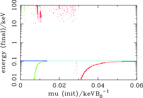
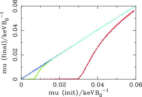
We test our particle solvers by releasing a population of electrons with gyrocentres at the origin, where the field strength is B=1.6875 B0. The electrons have a single energy of 0.1 keV such that the distribution in velocity space is a uniform spherical shell. This gives initial magnetic moments in the range m £ 0.0593 eV B0-1. The number of particles simulated was 105,000, which is similar to the number used in the simulations described in Chapter 5. In addition, our tests used an integration time of 3000 Wi-1, which is equal to the duration of the simulations.
The maximum magnetic field increase felt by electrons in our simulations is about Bmax » 10 Binit. The only electrons in our test simulation to reflect in fields larger than this have low magnetic moments of m <~0.006 eV B0-1. We need our test particle code to conserve energy and magnetic moment for electrons with m above this range.
Figure 3.2 compares the energy and magnetic moment conservation properties of the fourth order Runge-Kutta method and implicit leapfrog scheme. This is done by plotting the final value of the energy and magnetic moment against the initial value of the magnetic moment. The fourth order Runge-Kutta scheme is shown with Dt = 0.1 We-1 and Dt = 0.02 We-1. The implicit leapfrog scheme, whose computational speed is comparable with the Runge-Kutta scheme, is shown with Dt = 0.1 We-1.
The Runge-Kutta scheme with Dt = 0.1 We-1 has poor m and energy conservation for all values of minit and fails to conserve both by more than a factor of two for minit £ 0.04 eV B0-1. With Dt = 0.02 We-1, the Runge-Kutta scheme performs better, conserving m and energy to within a few percent when minit ³ 0.01 eV B0-1. Below this value, however, the conservation is very poor and the final values of m and energy drop to around zero. This is likely to affect the electrons in our simulations that experience the greatest field changes. The implicit leapfrog scheme with Dt = 0.1 We also conserves m and energy to within a few percent, but for a larger range of minit ³ 3 ×10⁻⁴ eV B0-1. At magnetic moments below these thresholds, the test particles in all the schemes encounter very high field gradients that cause numerical errors. According to our results, this would be problematic for the Runge-Kutta scheme. None of the electrons in our simulation are likely to experience field gradients that are sufficiently large for this to affect the implicit leapfrog scheme.
The Fourth Order Runge-Kutta method performs surprisingly poorly. It suffers from a systematic energy loss aggregated over a large number of time steps. The implicit leapfrog scheme, shown with Dt = 0.1 We, clearly has superior conservation properties for both energy and magnetic moment. This is the electron trajectory integrator that we chose for our simulations, for which we used a time step Dt = 0.05 We-1. There is evidence that varying the electron time step has an effect on our simulation results and the reasons for choosing Dt = 0.05 We-1 are given in Section 6.1.1.
energy_dipole
mu_dipole
Figure 3.2: Graphs illustrating the conservation properties of electron trajectory integrators. The intensity of the boxes represents particle number density on a logarithmic scale. The fourth order Runge-Kutta scheme is shown with Dt = 0.1 We-1 (red) and Dt = 0.02 We-1 (green). The implicit leapfrog scheme is shown with Dt = 0.1 We-1 (blue).

3.4  Field Interpolation

Krauss-Varban et al. [1989] found that high frequency fluctuations in the electric field were a significant cause of scattering in electrons' v^. In addition, we found that our electron integrator had stability problems at the shock front when the spatial grid spacing was too large. It therefore seems that the choice of field interpolation algorithm is important in studying test particle trajectories. We discuss a selection of interpolation schemes here, the algorithms for which are based on the discussion given in Press et al., [1992].

1-D interpolation

A 1-D interpolation is suitable for the temporal interpolation of our field data. If time, t, lies between time steps t0 and t1, which are separated by a time Dt, then we define the following:
A =  t1 - t

Dt
, B = (1-A) =  t - t0

Dt
(3.73)
Bilinear interpolation is a simple linear interpolation method that takes the form
f(t) = A f0 + B f1
(3.74)
A more sophisticated method of interpolation is the cubic spline. This allows us to interpolate the function in such a way that its first derivative is smooth and hence its second derivative is continuous. To see how this is achieved, let us first consider the case where we know the function's second derivative, f". We then add a correction term to Equation 3.69
f(t) = A f0 + B f1 + C f0" + D f1"
(3.75)
Under the condition that f(t) must tend to the prescribed values of f and f" at t0 and t1, the lowest order solution for C and D is
C =  1

6
(A3-A) Dt2, B =  1

6
(B3-B) Dt2
(3.76)
By differentiating Equation 3.70 and requiring this derivative to be continuous at the cell boundaries, we obtain a restriction on f":
f-1" + 4f0" + f1" = 0
(3.77)
The system is closed by specifying f" at the boundaries. These values are usually either calculated or set to zero to give a "natural" spline. This system of equations is implicit, but Equation 3.72 is also tridiagonal, so the system can be solved at reasonable computational expense in O(N) operations, where N is the number of time steps across which the interpolation is made.
Our field data vary slowly over time. Field time steps in a hybrid code are based on ion time scales, which differ from electron time scales by the order of the mass ratio mp/me, which is around 2000. A typical electron has a very high speed with respect to these field time steps, so it will travel across a number of spatial grid cells in a single field time step. This means that a high accuracy temporal interpolation is not required for the test particle code. We have therefore used a bilinear method for interpolation in time as the additional accuracy of the spline method is not worth the considerable trade-off in complexity and computational time.

2-D interpolation

grid_cell
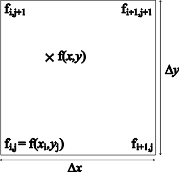
Figure 3.3: Labelling of quantities within a grid cell.
A 2-D interpolation is required for spatial interpolation of the fields. If (xi,yj) is the grid point to the bottom left of a given position (x,y) then we will label quantities within a grid cell as shown in Figure 3.3 and define the following:
a =  x - xi

Dx
, b =  y - yj

Dy
(3.78)
The bilinear interpolation equation in 2-D is:
f(x,y) = (1-a) (1-b) fi,j - a(1-b) fi+1,j + abfi+1,j+1 - (1-a) bfi,j+1
(3.79)
The bicubic interpolation method adds to this by using the derivatives of the function f at the four corners of the grid cell:
 f

x
,  f

y
,  2 f

x y
(3.80)
In our case, since we do not know these derivatives, we calculate them numerically using centred differencing:
æ
è
 f

x
ö
ø


i,j 
=  fi+1,j - fi-1,j

2 Dx
(3.81)

æ
è
 f

y
ö
ø


i,j 
=  fi,j+1 - fi,j-1

2 Dy
(3.82)

æ
è
 2 f

x y
ö
ø


i,j 
=  fi+1,j+1 - fi+1,j-1 - fi-1,j+1 + fi-1,j-1

4 Dx Dy
(3.83)
The bicubic interpolation equation in 2-D uses these sixteen quantities via a linear interpolation equation (Equation 3.79). This equation involves a linear transformation matrix, C, which depends on the partial derivatives and is described in Press et al. [1992]:
f(x,y) = 4
å
a=1 
4
å
b=1 
Cab  aa-1 bb-1
(3.84)
An alternative way to calculate the required derivatives is through the use of global 2-D splines. The actual process of interpolation is equivalent to 2-D bicubic interpolation. This interpolation scheme consists of two stages. The first stage produces an auxiliary table of spline coefficients in the x-direction. The second stage uses these coefficients to evaluate values in a line parallel to the y-axis with an x-coordinate equal to the position of the required value. A spline is then constructed to pass through all these points and a final spline evaluation is used to determine the final interpolated value.

Scheme comparison

Bx_interp
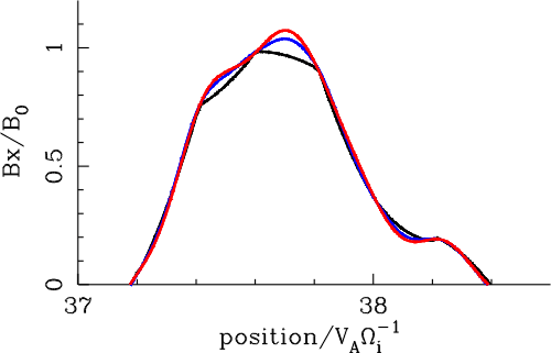
Figure 3.4: Graph comparing the Bx field component interpolated using different interpolation schemes. The interpolation methods used are bilinear (black), bicubic (blue) and splines (red).
Figure 3.4 compares the fields determined using different interpolation schemes along a single field slice. The slice was taken along the line y=x from the shock simulation shown in Figure 4.2. The bilinear scheme is significantly faster than the other two interpolation schemes. However, bilinear interpolation produces discontinuities in the value of the field gradient, which would correspond to the introduction of high frequency field structure. Bearing in mind the results of Krauss-Varban et al. [1989], which show that high frequency field structure is responsible for numerical scattering of electron pitch angles, this is clearly an undesirable characteristic.
The bicubic and spline interpolations provide similar results in that they both enforce smoothness of the field gradient. Spline interpolation does, however, produce a larger overshoot where the field reaches a turning point. It also requires us to specify boundary conditions at the edge of the simulation box, which may lead to the creation of artifacts. It is also an implicit scheme, which has the undesirable property of allowing distant field structures to have an influence on local field properties. The bicubic scheme is explicit and does not suffer from these drawbacks. In addition, it has a lower computational cost and is easier to implement. We have therefore used the bicubic method for spatial interpolation in our electron trajectory integrations.


Page Maintained By : Rob Lowe
Last Revision : 1st March 2003